My FabAcademy Final Project
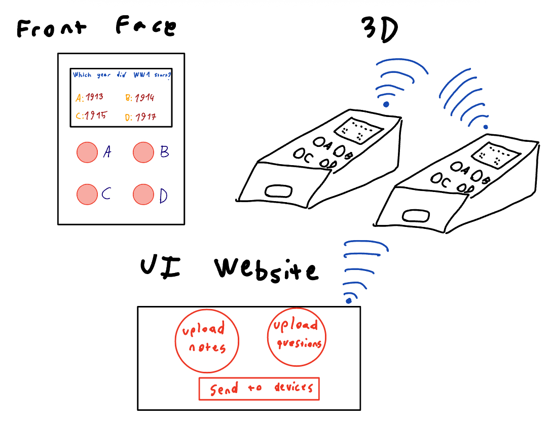
Sketch
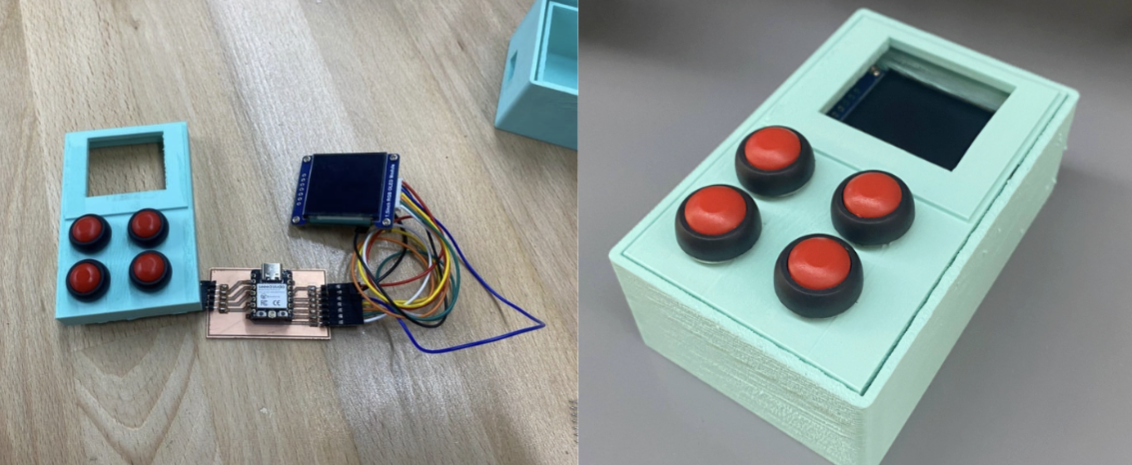
Hero Shot
Description
My Project is an interactive learning device that takes inspiration from the “Quizlet” app and teaches students concepts that they want to learn using flashcards, questions, quizzes and even live competitions. Students can upload their notes through the website and an AI model can generate questions or flashcards for the user to study the material.
Feedback
- xiao esp antenna positioning is important for wifi connection
- vinyl cut wires between boards for height diff can be impressive cool additional feature
- A, B, C, D, not flashcards.
- First focus on one device, then expand to two for two player competition
- Plan the game design and how game will be before starting (Creative competition learning games)
- Hardcoded wifi
- Use multiple fabrication methods and integrate as much as the weeks as you can with the final projects.
Ideas
- Vinyl sticker on top.
Wiring Plan
Based on the datasheet information, I created a wiring plan that connects the ESP32-C3 to an RGB OLED display and four push buttons.
OLED Display (SSD1351, 4-Wire SPI)
The OLED uses the SPI protocol, which is supported by several pins on the ESP32-C3. I assigned the following connections:
| OLED Pin | ESP32-C3 Pin | Function |
|---|---|---|
| VCC | 3V3 | Power supply (3.3 V) |
| GND | GND | Common ground |
| SCK | D9 | Serial Clock |
| MOSI | D10 | Serial Data (Master → Slave) |
| RST | D6 | Display Reset |
| DC | D8 | Data/Command control |
| CS | D7 | Chip Select |
This pin mapping ensures smooth SPI communication between the ESP32-C3 and the OLED while keeping all logic levels at 3.3 V.
Push Buttons
Each push button is connected between a GPIO pin and ground. The ESP32-C3’s internal pull-up resistors will be enabled in software, so the default state of each pin is HIGH, and pressing a button pulls it LOW.
| Button | ESP32-C3 Pin | Connection |
|---|---|---|
| BTN1 | D0 | Connected to GND |
| BTN2 | D1 | Connected to GND |
| BTN3 | D2 | Connected to GND |
| BTN4 | D4 | Connected to GND |