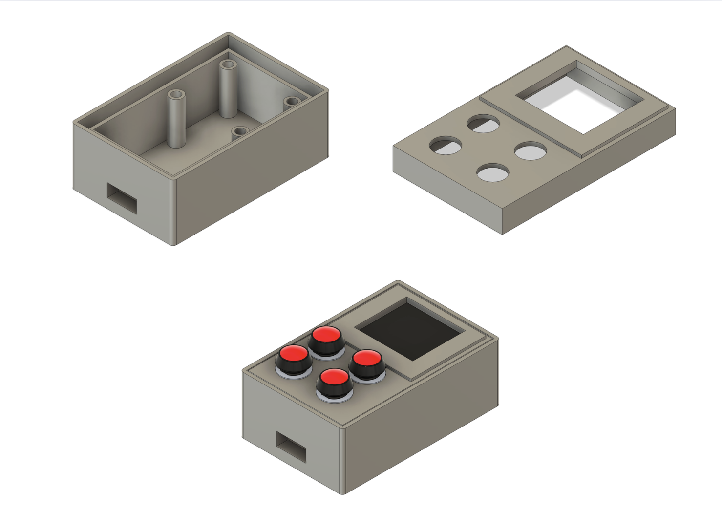
This week is an introduction to CAD (Computer-Aided-Design) where we model in both 2D and 3D. I learned parametric design, constraints and user parameters during this week, which are very important fundementals of Computer Aided Design. You can access my design files at the bottom of the page.
Learning Objectives
- Evaluate and select 2D and 3D software
- Demonstrate and describe processes used in modelling with 2D and 3D softwares
- Demonstrate image and video compression
Hero Shot
2D Design
To model in 2D you can use a raster based program or a vector based program.
In a raster program, we make use of the concept of a rectangular field of pixels and you define the color and transparency of each pixel. My raster program of choice was Adobe Photoshop.
In a vector program, we utilize mathematical formulas and paths to define each shape. The biggest advantage is that the vector designs can be scaled without loss. My vector program of choice was Adobe Illustrator. Vector programs are best when working with machines.
So very basically raster programs work with pixels while vector programs work with mathematical calculations.
Raster Based
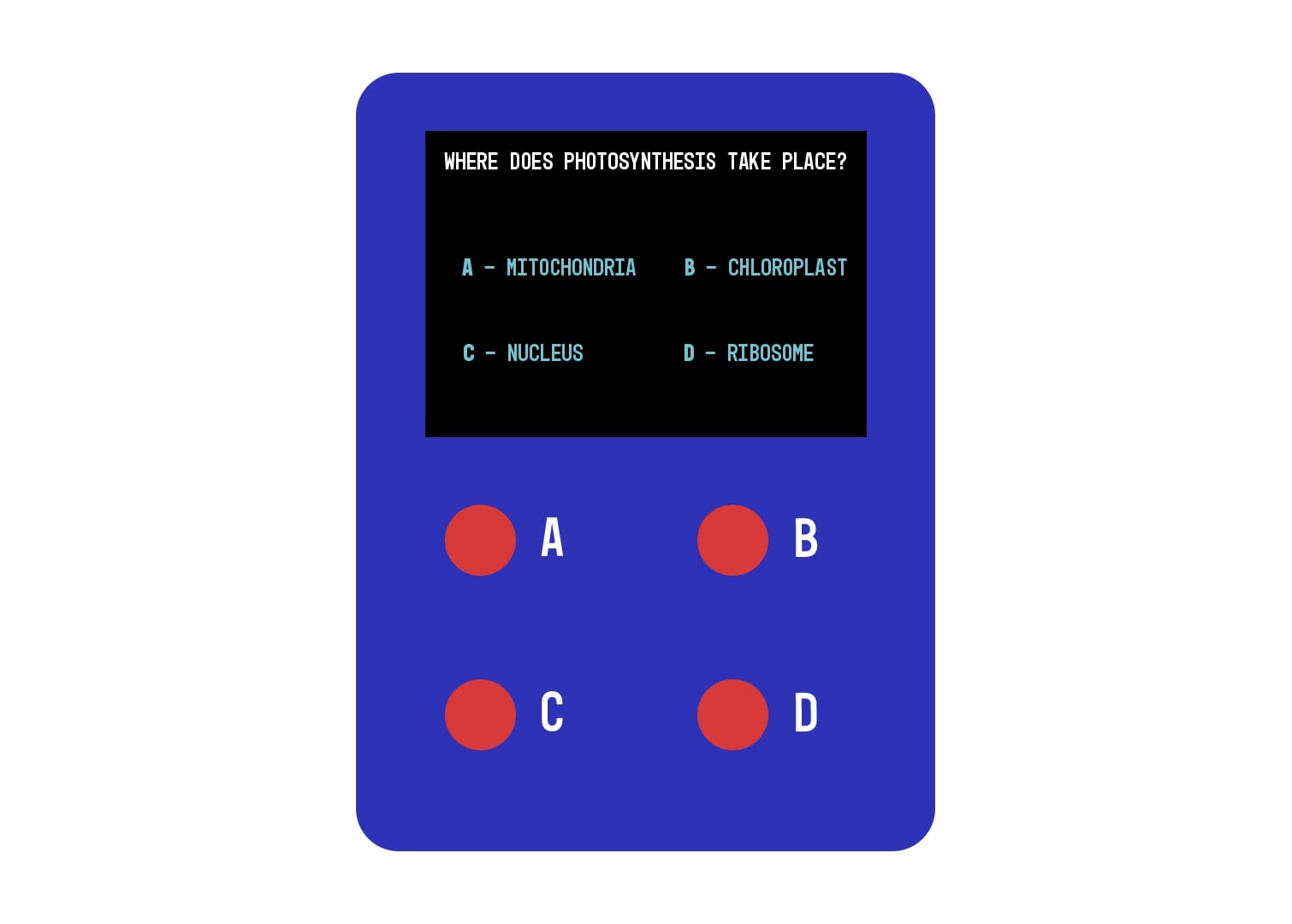
I used the raster based portion to focus on the design my device, which includes a screen and four buttons. In Adobe Photoshop, I created the user interface for the screen and laid out the overall visual design of the device to guide the later fabrication process.
Note: This design is exported in .jpg format and is not made for fabrication, it’s only made to sketch and plan the device’s layout.
Below you can see my final design made on Adobe Photoshop where I sketched out the device:
Vector Based
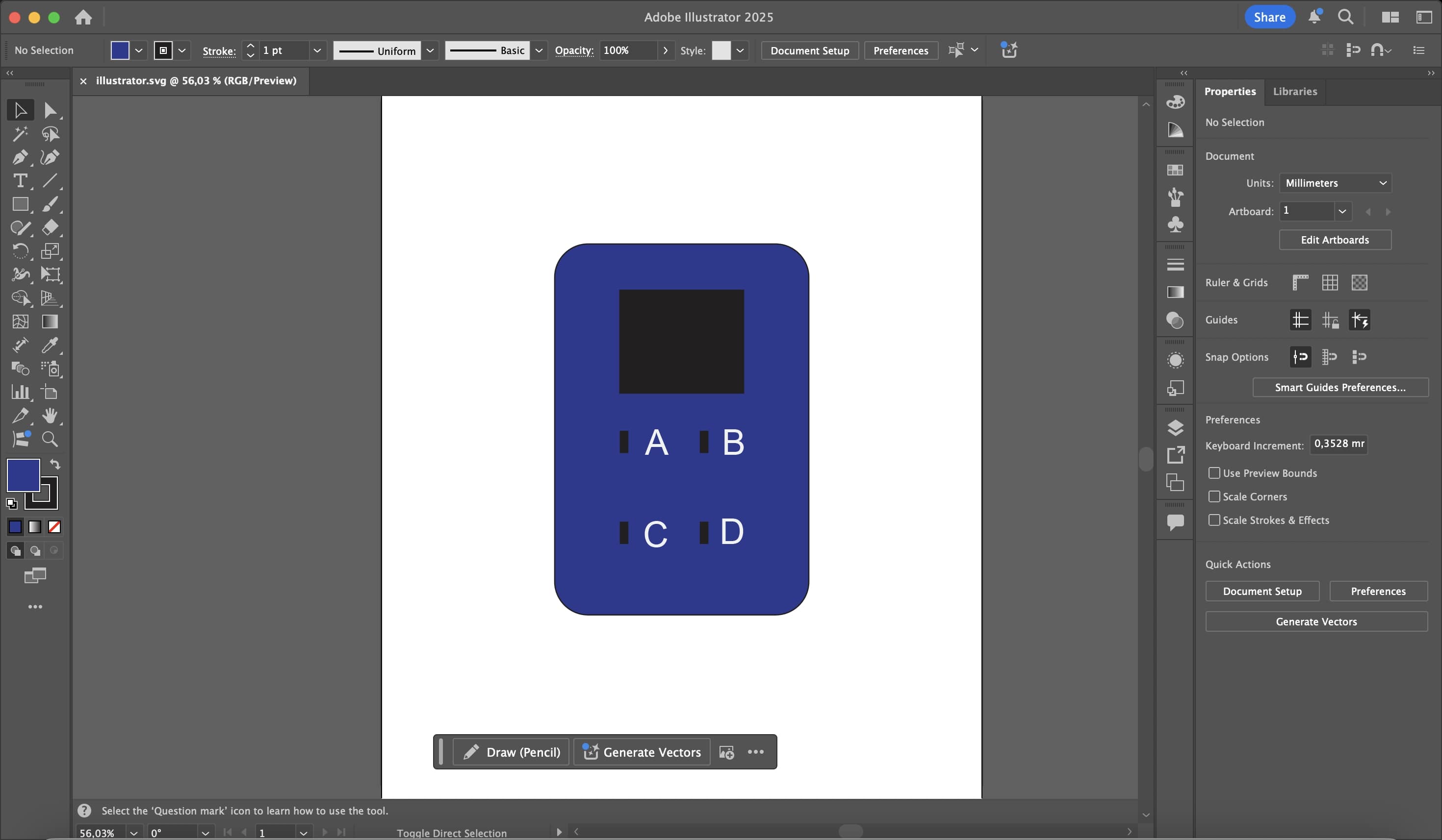
I used the vector based portion to experiment with creating a design which will later be exported in .svg format and fabricated. This file format is important because it can directly be used on laser cutters. This design process helped me to understand the difference between raster and vector based programs because I understood that raster based programs are used for a design purpose while vector based programs can be used for fabrication purposes. This design has holes that are purposed to be cut where the screen and buttons can be mounted.
Vector based programs work with boolean operations like union, difference and intersection.
Note: You can model vector based 2D inside 3D software but you can also produce fabricatable files using vector based 2D design tools.
Below you can see my final design made on Adobe Illustrator where I designed the device:
3D Modelling
I was completely new to 3D modeling starting out and I failed and redesigned multiple times when designing. I used Fusion360 for the designing as it was the software that offered the most intuitive and powerful set of tools for parametric modeling. I modeled my device in 3D, including the screen housing and four buttons, aligning it with my 2D design. Through several iterations of trial and error, I refined the dimensions and layout to ensure the model was both realistic and ready for fabrication. I also used models from GrabCAD to design on the electronic components of my design.
During this process, I began by creating 2D sketches for the top face of the device, defining the boundaries of the screen area and the four button cutouts. I used constraints like equal spacing, coincident points, and fixed dimensions to make the sketch fully constrained. After completing the sketches, I extruded the main body and applied the shell tool to create a hollow interior for the electronics. I defined user parameters such as thickness, button_diameter, and screen_width, which made it easier to quickly adjust and iterate on the design without redrawing sketches.
Next, I imported the downloaded GrabCAD models of the screen and buttons and scaled them properly to ensure accurate proportions. I placed these parts using the assemble → joint feature, aligning them precisely within the body. This helped me verify fit and clearance between components. I experimented with fillets on the corners and button housings to improve both the aesthetic and ergonomic aspects of the design. I also added small support features inside the model to hold the screen more securely and prevent movement once assembled.
The final 3D model represents my complete design, a compact device body featuring a recessed screen area and four tactile buttons positioned in a grid layout. Each button is enclosed within a square housing, and the screen is angled slightly for better visibility. I also incorporated detailed mounting points, clearances, and rounded edges to make the model practical for 3D printing. The proportions were refined multiple times to balance usability and aesthetics, resulting in a realistic, fabrication-ready prototype that closely matches my initial 2D concept.
Additionally, I exported the model in both .f3d and .stl formats — .f3d for future parametric edits and .stl for slicing in a 3D printer.
Here you can see the design process using the timeline tool in F360:
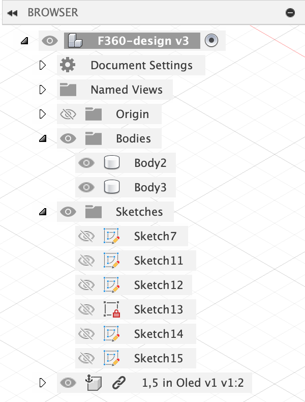
Here you can see the layers of my F360 design:
Here you can see my v1 hero shot:
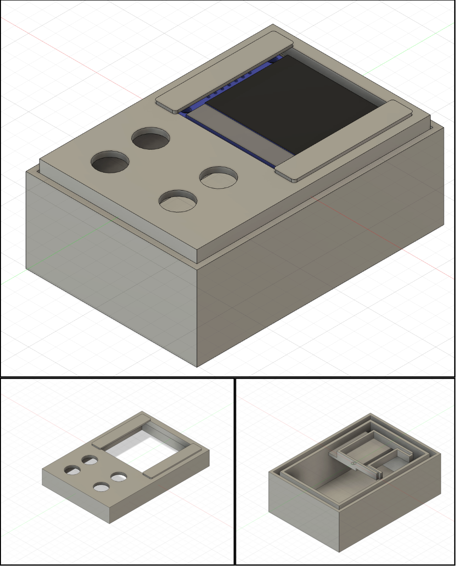
Then I changed some parts of my design after printing it and getting some feedback. First of all the screen holder was very impractical. I changed the screen holder to be 4 cylinders extending from the floor of the inside of the model. Also some measurements didn’t exactly fit my components because the GRABCAD models didn’t exactly match the real life version. So I needed to change that too. Also I needed to add 0.2 mm tolerance for the printers.
Below you can find the final design after all of the changes:
Below is the timeline where you can see the full design process from start to finish:
Blender (3D Animation)
In addition to parametric modeling in Fusion 360, I also used Blender to explore basic 3D animation workflows.
Rather than redesigning the model from scratch, I imported my final Fusion 360 design directly into Blender and focused on visualizing the assembly process through animation.
The model was exported from Fusion 360 and imported into Blender as two separate parts. This allowed me to animate how the device comes together, rather than only showing a static final geometry.
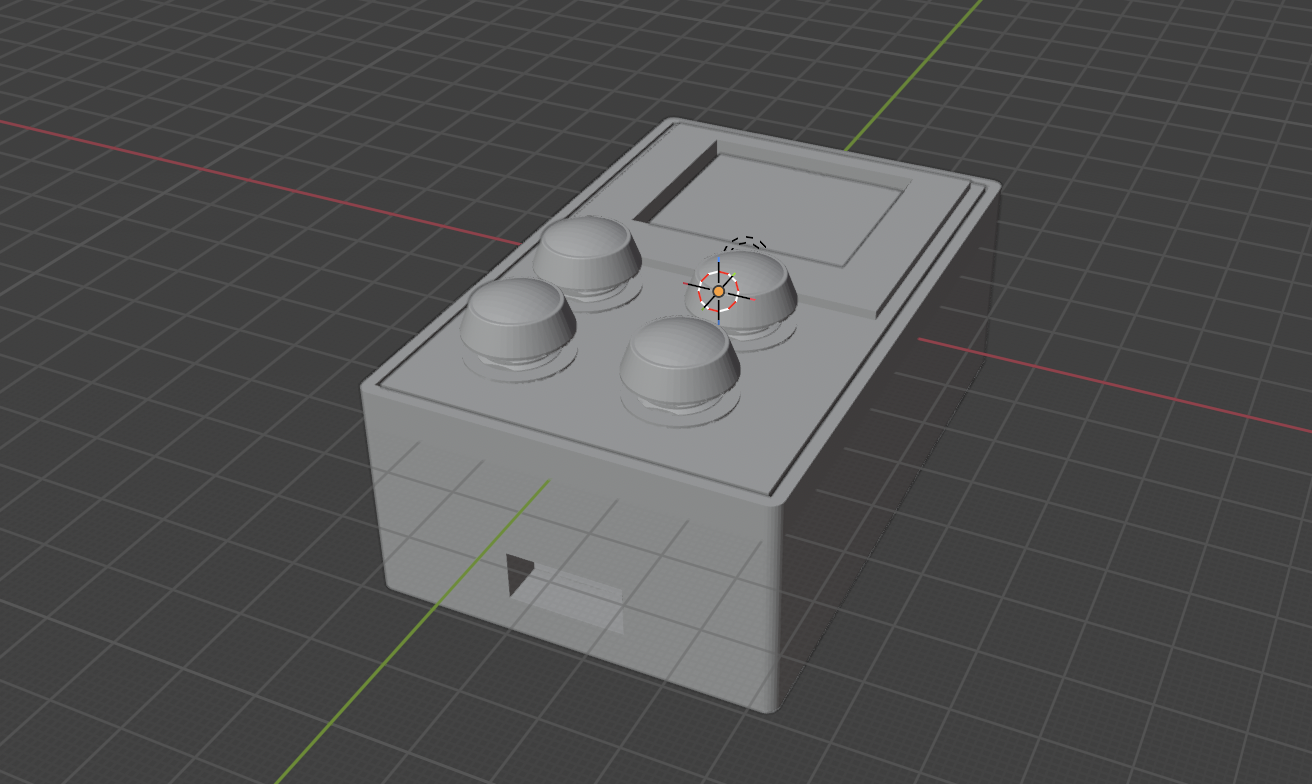
Below you can see the imported model in Blender where the two parts are already assembled:
Below you can see the same design in Blender with the two parts separated before animation:
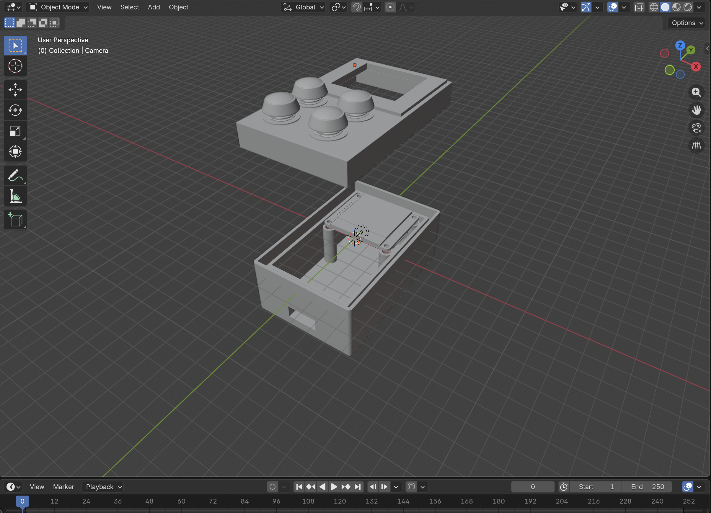
To create the animation, I used keyframe-based animation in Blender. I defined the position and rotation of each part at different frames on the timeline and interpolated their motion so that the two parts smoothly move into place, forming the final assembled device. This helped me understand Blender’s timeline, transformation tools, and animation workflow.
The animation represents the assembly sequence of the device rather than a physical simulation, making it useful for visually communicating how the design is structured and how components relate to each other.
Below you can see the final rendered animation:
The original .blend file was saved as part of the design files to preserve the full animation timeline and ensure reproducibility.
Note
Images were resized and compressed before uploading to keep the documentation lightweight and fast to load.