Learning Objectives
- Implement programming protocols.
1. Introduction
This week, the objective was to explore the microcontroller datasheet, understand its capabilities, and then write and simulate a program that interacts with local input devices and communicates with a remote device through a wired or wireless protocol.
For this assignment, I used the ESP32-C3 Super Mini, built around a RISC-V core.
My program reads four push buttons and communicates the button state to my computer via USB serial, which qualifies as a remote wired communication interface.
2. Browsing My Microcontroller Datasheet
The ESP32-C3 is a compact RISC-V microcontroller featuring:
- 3.3 V logic level
- Multiple GPIO pins configurable as digital I/O, ADC, I²C, SPI, PWM, or UART
- Built-in USB-Serial interface (UART over USB)
- Low power consumption modes
- Wi-Fi (2.4 GHz) and Bluetooth LE support
Below is the pinout diagram I used:
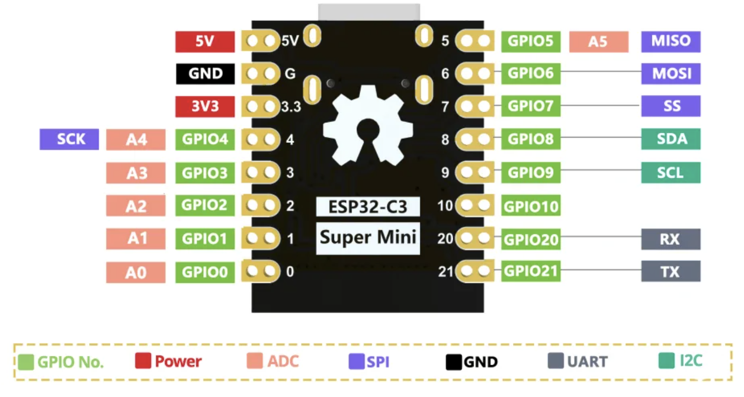
Key things I learned from the datasheet
- GPIO pins can be reconfigured into different peripheral modes (SPI, UART, I²C, PWM).
- GPIOs support internal pull-up resistors, which is perfect for button inputs.
- The USB-Serial interface is always available for debugging/communication.
- All logic levels are 3.3 V, making it safe for many sensors and displays.
- Several pins (GPIO4–7, 10) support SPI, which I will later use for my OLED display.
This information was essential for planning my wiring and programming.
3. My Wiring Plan
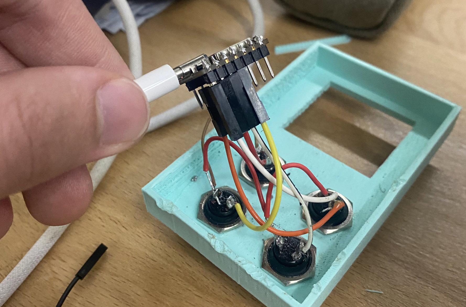
For this week’s assignment, I focused on four push-buttons connected to the ESP32-C3, which act as local input devices.
I later plan to use the OLED display, but for this week, only the buttons were required.
Push Button Connections
| Button | ESP32-C3 Pin | Function |
|---|---|---|
| BTN1 | GPIO2 | Input + Pull-Up |
| BTN2 | GPIO3 | Input + Pull-Up |
| BTN3 | GPIO4 | Input + Pull-Up |
| BTN4 | GPIO5 | Input + Pull-Up |
Each button is connected between its GPIO pin and ground.
The ESP32-C3 internal pull-ups keep the pin HIGH when not pressed, and LOW when pressed.
Why this meets the assignment criteria
- Buttons = local input interaction
- Serial output = remote wired communication
- Simulation/programming = microcontroller workflow
- GPIO analysis = datasheet usage
Finished Wiring
4. Programming the ESP32-C3
I wrote a program in the Arduino IDE in C++ that:
- Reads all four buttons
- Detects a new press event (edge detection)
- Uses debouncing
- Prints which button was pressed over USB serial
This communicates with a remote wired device (my laptop) using UART-over-USB.
Why I Chose Arduino IDE
I selected the Arduino environment because:
- It provides fast prototyping and very readable code.
- The ESP32-C3 boards have excellent Arduino core support.
- Serial communication, GPIO input, and debounce logic are straightforward.
- I could quickly test button logic without a complex build system.
- It integrates well with the USB-Serial bridge on the ESP32-C3.
Source Code
// ESP32-C3 Button Option Selector
// GPIO2 → Option A
// GPIO3 → Option B
// GPIO4 → Option C
// GPIO5 → Option D

int buttons[] = {2, 3, 4, 5};
const char* labels[] = {"Option A", "Option B", "Option C", "Option D"};
int lastState[4];

void setup() {
  Serial.begin(115200);
  delay(500);
  Serial.println("\nESP32-C3 Option Button Test");
  Serial.println("Press any button (GPIO 2–5)...\n");

  for (int i = 0; i < 4; i++) {
    pinMode(buttons[i], INPUT_PULLUP);
    lastState[i] = HIGH; // not pressed
  }
}

void loop() {
  for (int i = 0; i < 4; i++) {
    int current = digitalRead(buttons[i]);

    // Detect new press (HIGH → LOW)
    if (current == LOW && lastState[i] == HIGH) {
      delay(10); // debounce
      if (digitalRead(buttons[i]) == LOW) {
        Serial.print(labels[i]);
        Serial.println(" pressed!");
        lastState[i] = LOW;
      }
    }

    // Update when released (no print)
    if (current == HIGH && lastState[i] == LOW) {
      lastState[i] = HIGH;
    }
  }
}
Programming Protocols Used
- Digital input scanning
- Hardware pull-ups
- Software debouncing
- Serial communication
(UART over USB → remote wired communication)
Problems I Faced
1. Button Bouncing
Symptom: Pressing once would sometimes print the label two or three times.
Cause: Mechanical switches physically bounce when pressed.
Fix: Added delay(10) which eliminated bounce events. Added edge detection (HIGH → LOW) instead of continuous prints.
2. False Triggers
Symptom: Sometimes a button “pressed” message appeared without touching anything.
Likely Cause: Noisy floating values read during transitions Internal pull-ups not yet engaged (startup stage) Loose breadboard connection
Fix: Set all pins as INPUT_PULLUP Added startup delay of 500 ms Ensured wires were firmly seated
5. Testing & Demo
Below is the demo video showing the buttons working and the serial messages printing when each button is pressed:
This confirms that the microcontroller:
- interacts with local input devices
- communicates with a remote wired device (my computer)
6. What I Learned
- How to use the ESP32-C3 internal pull-up resistors
- How to read button states reliably
- Using UART serial prints for debugging and communication
- How to debounce buttons in software
- Understanding pin multipurpose functionality from the datasheet
- How to implement edge detection (state change detection)
- How to structure a clean embedded program for multiple inputs
7. Group Project
You can check our group project here