Learning Objectives
- Demonstrate workflows used in controlling an output device(s) with MCU board you have designed.
Hero Shot
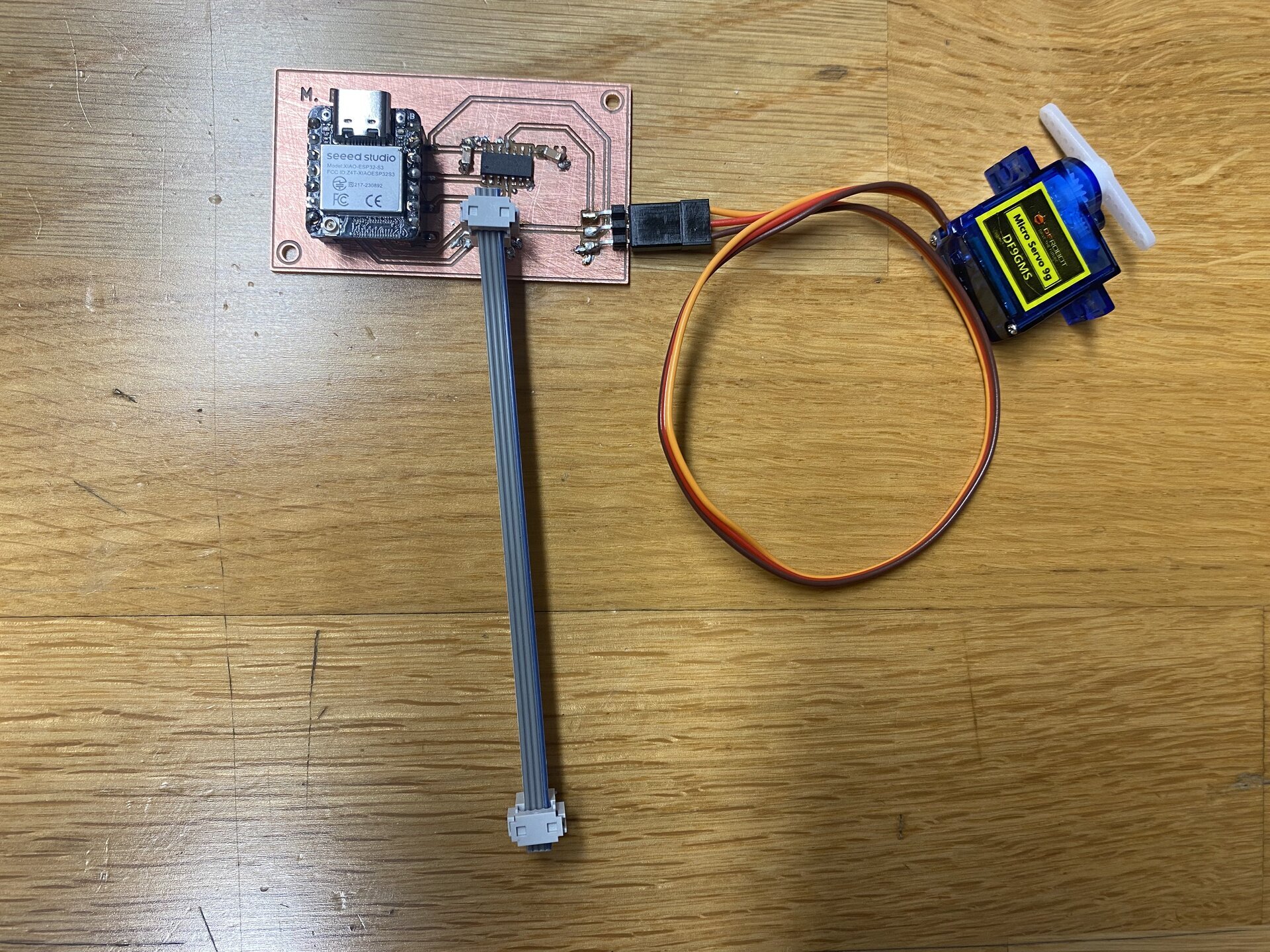
1. Introduction
The goal of Week 10 was to add an output device to a microcontroller board I previously designed (Week 6) and program it to do something.
I used my custom ESP32-C3 board and controlled a continuous rotation servo motor using PWM.
2. Determining Power Consumption
For the servo:
- Voltage: 5V
- Idle: ~10–15 mA
- No-load rotation: ~100–150 mA
- Stall: up to ~700 mA
This showed the servo must run from a 5V supply, not from the ESP32’s 3.3V regulator, and that I needed a 3.3 → 5 V level shifter.
To correctly drive my continuous-rotation servo, I reviewed the manufacturer datasheet. The key specifications I used for my power calculations and PWM programming were taken directly from the sheet.
Key Specifications From Datasheet
- Operating Voltage: 4.8–6.0 V
- No-Load Current: ~100–150 mA
- Stall Current: up to ~700–800 mA
- Control Signal: Standard PWM (50 Hz)
- Pulse Width Range: ~1000–2000 μs for full speed
These values guided my design decisions:
- The servo must be powered from 5 V, not 3.3 V
- It cannot be powered from the ESP32-C3 regulator
- The ESP32 PWM (3.3 V logic) must be level-shifted to 5 V
3. Connecting the Servo to My Board
After confirming my ESP32-C3 powered on:
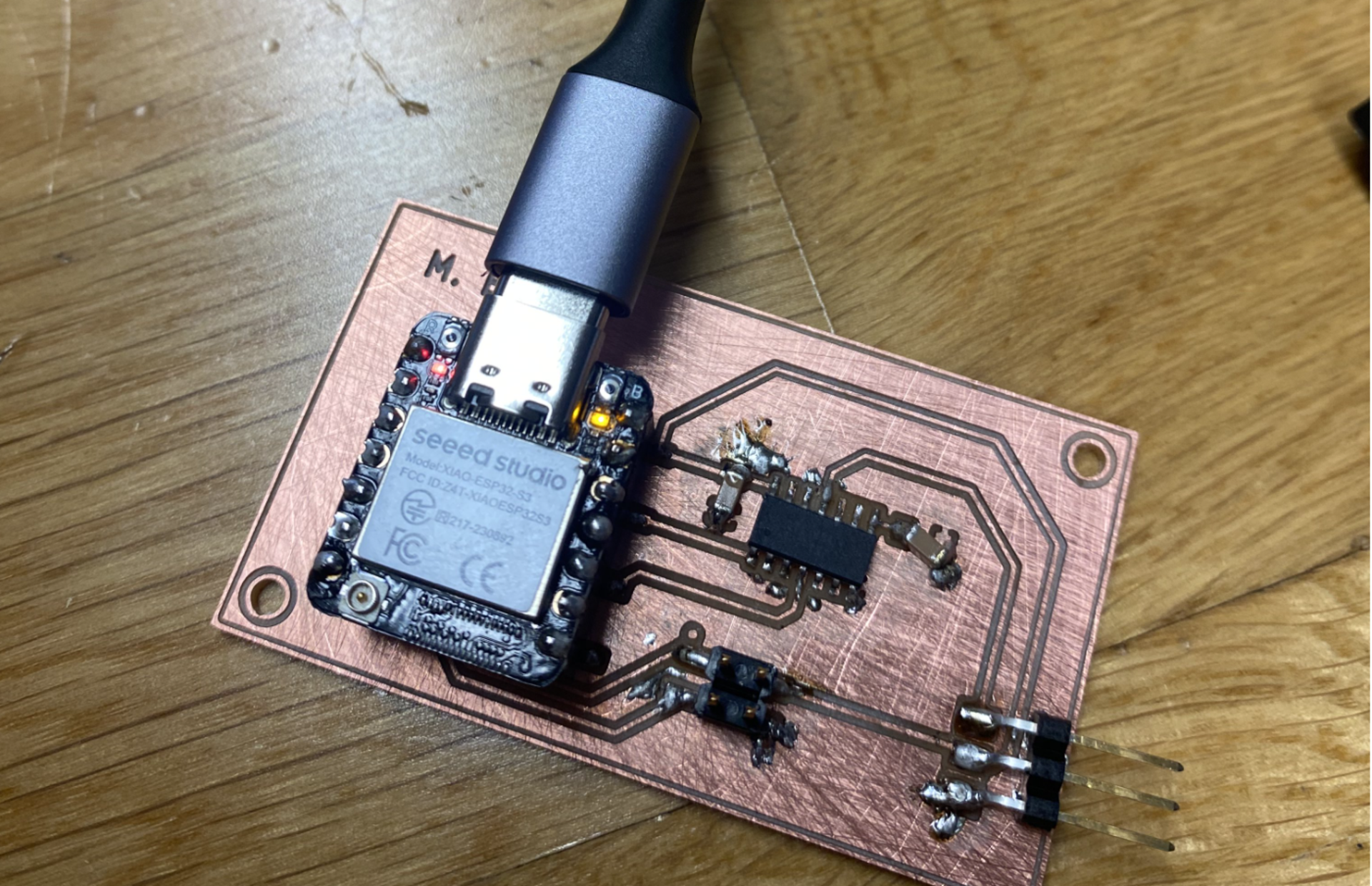
I connected:
- 5V
- GND
- Level-shifted PWM pin
All through the 3×1 header I designed earlier.
4. Programming the Servo
Below is the exact code I used.
#include <ESP32Servo.h>

Servo s;

void setup() {
s.setPeriodHertz(50);
s.attach(8, 500, 2500);
}

void loop() {
s.writeMicroseconds(2000);
delay(3000);
s.writeMicroseconds(1500);
while (true);
}
Explanation
setPeriodHertz(50)→ standard servo refresh rateattach(8, 500, 2500)→ pin + min/max pulse2000µs→ full-speed rotation1500µs→ stop
This confirmed the signal path:
ESP32 3.3V PWM → Level Shifter → Servo Input (5V logic)
5. Working Demo
6. Problems & Fixes
Short between 5V and copper island
Fixed by removing excess solder.
NC pins shorting to GND
Fixed using flux + wick.
7. What I Learned
- Correctly driving a servo from a custom microcontroller board
- Level shifting for 5V signals
- Measuring power consumption
- PWM control with
writeMicroseconds() - Debugging shorts and orientation issues
- Completing the full design → production → programming cycle
8. Group Project
You can check our group project here